Snagpad Plus Build Guide
Tommy ThaiIN PROGRESS - 23/10/2025
Step 0 - Flashing the Seeed Xiao
Have a computer and a connected USB Type-C cable ready. To make the microcontroller work as a keyboard, we will need to change the Seeed Xiao firmware to our custom .UF2 file
- Open and remove the Xiao from the plastic packaging.
- Press and hold the Boot Button (labelled B) while connecting the USB C cable. This is how we enter Bootloader mode and the Microcontroller will now show up in your computer’s device list (similar to a USB Stick).
- Drag and drop the .UF2 bootloader file to this new Seeed Microcontroller device.
If everything was done correctly, the Microcontroller will disappear from the device menu and your computer will show a notification confirming “Snagpad Plus” has been connected successfully.
Download Bootloader File - idyllic_snagpad.uf2
https://cdn.shopify.com/s/files/1/0599/5914/8737/files/idyllic_snagpad.uf2?v=1761208752
- Keep the microcontroller connected and open VIA - https://usevia.app/.
A pop-up box should appear; select "Snagpad Plus" and click the "Connect" button.
Afterwards press "Authorise Device +" if the prompt shows.
You may need to refresh the browser a few times if you are having issues detecting the keyboard.
- Go to the settings and enable the "Show Design Tab". This is because we need to load the JSON file as it has not been officially merged so won't auto detect your keyboard.
- In the Design Tab, load the JSON file into VIA. Your screen should look like the image below.

Download JSON File - Snagpad_plus_V5_VIA - Encoder.JSON
https://cdn.shopify.com/s/files/1/0599/5914/8737/files/snagpad_plus_V5_VIA_-_Encoder.json?v=1761209002
If everything seems correct and the Xiao Seeed is working with VIA, you can proceed to the next steps which involve soldering and assembling the kit.
Preparation:
Main PCB
Sockets – Install them the correct way. Don’t block the center hole
2) Diodes – Line on the PCB (square shaped hole) matches Line on the diodes. Install all the diodes.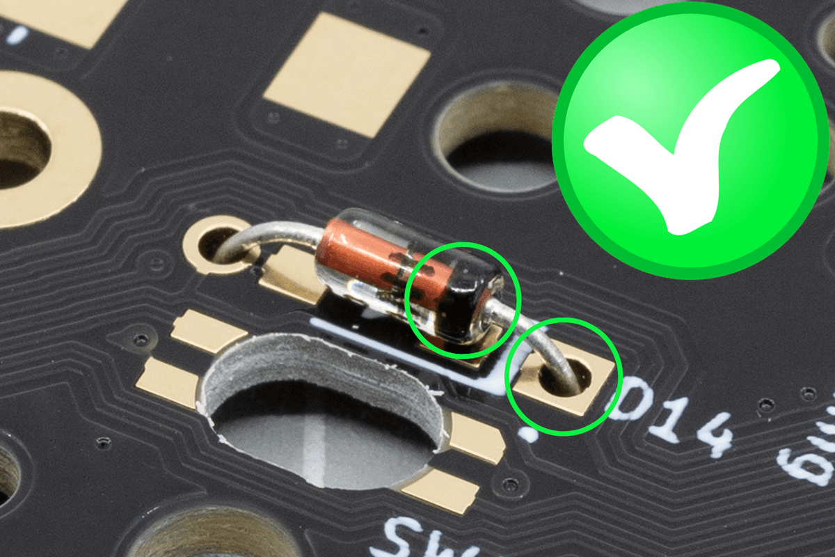
3) Header Pins (Male) – Install on the underside but solder from the top. You can try using the rectable on the 3D printed part to help hold it in place.
4) Rotary Encoder – You may need to bend the side pins of the Encoder to fit into the holes.
5) Bumpons – Install the two large white bumpons on the underside of the PCB
Daughterboard PCB
6) Xiao Seeed – Solder this to the pads on the PCB.
7) Header Pins (Female) – Install on the top (same side as the microcontroller) and solder from the underside.
Acrylic Base Plate
8) Install Bumpons
9) Peel Brown protective film
Assembly
After both PCBs are soldered, use the rectangle cutout on the 3D printer part to push the Male and Female header pins together.
Add the standoffs into the 3D printer part and align under the Main PCB and underneath the Xiao Seeed.
From the top, install the 2x smaller M3 screws into the standoffs under the Main PCB.
Flip everything over and align the holes in the acrylic base plate over the 3D printed part. Install the 2x larger M3 screws.